The Meccano Society of Scotland


Andrew Knox
Miscellaneous Mecanisms
Simple Mechanical Counter
(3 photos below)
Most counter mechanisms use a number of wheels with digits displayed around the circumference of the wheel. In operation, the wheel is rotated in steps to ensure the whole digit is fully visible, often using a maltese cross mechanism to convert the continuous rotary motion into a series of steps. For counters with multiple decades of digits the division between 10's, 100's, 1000's etc. becomes rather more complicated.
10 hole 2 ½" faceplates and ½" bolts are used to make simple peg-type gear wheels. Each meshes with a long bolt secured to the axle of the previous decade by a collar. This is used to knock the next decade wheel around by one position for each rotation of the axle of the previous stage. As many stages as desired can be cascaded. In the model shown the "units" pointer rotates continually but the 10's, 100's and 1000's pointers each move in steps of 1/10th of a revolution. In order to ensure all the pointers rotate in the same direction, intermediate gearing is used to reverse the direction of rotation between successive stages. Socket couplings holding small rubber collars are used to provide a small amount of friction between the rods holding the pointers and the frame of the mechanism. This is necessary to hold the pointers stationary between increments.
The small bush wheels are used to obtain the necessary clearance between the shafts for the '10's' pointer. The only critical adjustment in the mechanism is of the long bolts secured to the intermediate shafts using collars. Adjustment of one decade will depend on the previous decade being in the correct place. Also, the pointer movements have to be completed in a single turn of the units wheel as each roll-over occurs - e.g., between '9999' and '0000'. This can be a bit fiddly but with a bit of patience can be accomplished.
"Deltic" Phasing Gearbox and Opposed Piston Motion
(2 photos below)
The Napier Deltic engine is an opposed-piston valveless, two-stroke diesel engine used in marine and locomotive applications, designed and produced by Napier & Son. The cylinders were divided in three blocks in a triangular arrangement; the blocks forming the sides with crankcases located in each apex of the triangle, hence the name after the Greek letter delta (Δ). Each cylinder contains two pistons moving in opposite directions towards the centre, negating the requirement for a heavy cylinder head and thereby achieving a high power to weight ratio.
To ensure the correct motion of all the pairs of pistons, one of the crankshafts (the bottom one) has to rotate in the opposite direction to the others. The motion of each crank is re-combined in the Phasing Gearbox, shown in the Meccano model. With an equilateral triangular arrangement of the cylinders and the use of one contra-rotating crank, the phase difference around the engine is 60°. This phase difference is divided equally among the three cylinders giving a phase angle of 20° of crankshaft rotation. This means one piston must lead the other in each cylinder by 20° and this lead is given to the exhaust piston, also shown in the Meccano model. Commercial Deltic engines used six banks of three cylinders giving low torque ripple and torsional vibration by virtue of a "power stroke" every 20 mechanical degrees of crank rotation. Power output is taken from the gearwheel at the centre of the Δ.
The Meccano model shown in the photos uses a combination of Meccano and Marklin parts to implement the mechanism. The main construction difficultly lies in obtaining the axle spacing necessary for the pistons in each bank to come together but not actually touch if using bush wheels and 5 hole strips to simulate the crankshafts and con rods. For this reason, the Marklin slotted strips are used to form the Δ, and they are held loosely on the bushwheels' axles. The pistons are represented by the slide pieces. Adjustment of the mechanism takes time and needs to be undertaken methodically. The use of a protractor to obtain the correct crank angle relationships will help considerably.
Epicyclic Gearbox - SM61 from the 1935 Book of Standard Mechanisms
(3 photos below)
Building this model was relatively straightforward even though the description provided in the booklet is a bit sparse in places. Many of the construction details have to be worked out as the gearbox is being assembled and a couple of iterations were needed to convince myself that all the spaces and bracket positions were as intended. The only significant change required was the use of threaded collars rather than standard collars to space the 57T gear wheel from the 7 hole double angle strip.
Some time will be needed to adjust the respective positions of the gear wheels and pinions on their shafts so that gear changes can be effected without binding. However, once correctly adjusted, the gear change is remarkably smooth, aided by the addition of a compression spring to reduce backlash. There is no apparent practical reason for neutral to lie between first and second gears, instead of the more usual position of between reverse and first. Indeed, the mechanism may be adjusted for operation in this way quite easily, albeit with an altered order of meshing of gears.
Winding Drum with Planetary Reduction Gear
(1 photo below)
A pair of 19T 1/2" pinions mesh with a 38T and 40T pinion. The 38T pinion is fixed and the 40T pinion is attached to the axle of the winding drum. The planet gear carrier is formed from a 95T gear wheel which is free to rotate on the winding drum axle and the 19T pinions are free to rotate on their respective shafts. As the planet carrier rotates the 19T pinions keep the teeth of the 38T and 40T pinions in line. This results in a rotation of the 40T pinion of 2 teeth for every revolution of the 95T gear wheel., yielding a 20:1 reduction ratio.
Swash Plate mechanism
(2 photos below)
This mechanism converts reciprocating motion to circular motion using a circular plate as the "crankshaft". The reciprocating motion of 4 pistons whose motions are each 90 degrees out of phase with the next is modelled by 1/2" brass pulleys running inside sleeve pieces. All are contained within the larger cylinder formed by the 3 1/2" circular girders and curved plates. A 3 1/2" circular plate is supported by a swivel bearing whose collar is fixed to a short rod supported in the plate by a pair of short threaded couplings and the swivel bearing's boss is held centrally in the 3 1/2" circular girder. This connection enables motion with two degrees of freedom.
The "big end" connection between each piston and the circular plate is formed using further swivel bearings whose collars are freely mounted on pivot bolts journalled in angle brackets attached to the circular plate at 90 degree intervals. Circular motion is enabled by the use of a handrail coupling placed in a socket coupling, the opposite end of which is secured to a second 3 1/2" circular plate using a threaded boss. The handrail coupling is held in place by carefully adjusting its position on the rod between the two circular plates. The second circular plate is carried on a bushwheel whose rod is journalled in a pair of flanged girder frames. A brass flywheel and handle is added to the opposite end of the rod to enable the user to rotate the mechanism and see the resulting reciprocating motion.
Pictures of the Mechanisms
High resolution versions of the photos are also available for download if desired.

Photo - Andrew Knox
Front View of the Simple Mechanical Counter - Andy Knox (10/02/2011)
Click here to see higher resolution photo
Photo - Andrew Knox
Front View of the Simple Mechanical Counter - Andy Knox (10/02/2011)
Click here to see higher resolution photo

Photo - Andrew Knox
Isometric View of the Simple Mechanical Counter - Andy Knox (10/02/2011)
Click here to see higher resolution photo
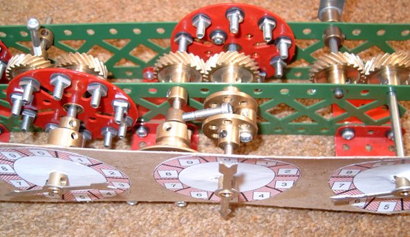
Photo - Andrew Knox
Close-up of the Simple Mechanical Counter - Andy Knox (10/02/2011)
Click here to see higher resolution photo

Photo - Andrew Knox
View of the 'Deltic' Gears - Andy Knox (10/02/2011)
Click here to see higher resolution photo

Photo - Andrew Knox
View of the 'Deltic' Pistons - Andy Knox (10/02/2011)
Click here to see higher resolution photo

Photo - Andrew Knox
Front View of SM61 - Epicyclic Gearbox - Andy Knox (10/02/2011)
Click here to see higher resolution photo

Photo - Andrew Knox
Back View of SM61 - Epicyclic Gearbox - Andy Knox (10/02/2011)
Click here to see higher resolution photo

Photo - Andrew Knox
Detailed View of SM61 - Epicyclic Gearbox - Andy Knox (10/02/2011)
Click here to see higher resolution photo

Photo - Andrew Knox
Winding Drum with Planetary Reduction Gear - Andy Knox (10/02/2011)
Click here to see higher resolution photo
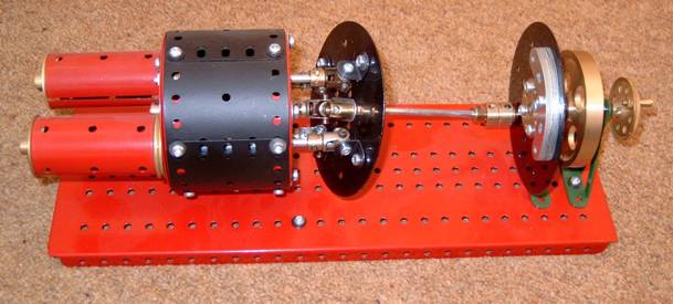
Photo - Andrew Knox
View of the Swashplate Mechanism - Andy Knox (10/02/2011)
Click here to see higher resolution photo

Photo - Andrew Knox
Close-up of the Swashplate Mechanism - Andy Knox (10/02/2011)
Click here to see higher resolution photo
Tip - You may find it better to view the pictures in 'full screen' mode - For most browsers F11 will toggle this on and off.
© 2024 Meccano Society of Scotland